English (UK)
 Français (FR)


This photo report illustrates the magnetic rope testing (MRT) of two overhead travelling cranes with a lifting capacity of 175 tons used together to handle alternator groups. The work required is to carry out the MRT diagnosis of the 6-strands times 61-wires lifting steel wire ropes with a diameter D=55mm and featuring an IWRC metallic core. The inspectable sections of the ropes are namely:
- the rope section wound on a single-layer winch,
- the rope section called "dead point" between the mooring at hook level and the fixed anchoring.
The objective is to assess the level of inner damage to the cables, mainly by wire breakage due to fatigue and/or internal wear, and to decide on their suitability for future use.


Inspection of winding section on winch
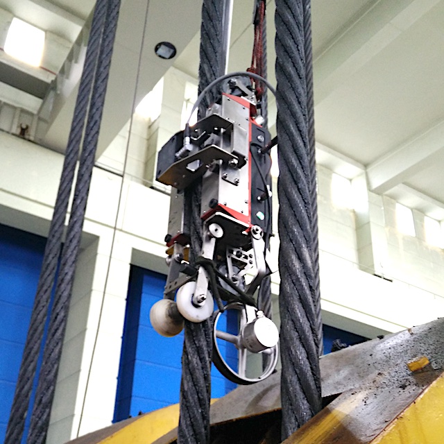
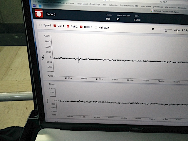
The section of cable stored on the winch was inspected by securing the state-of-the-art Rotec U58 machine to the right of the winch using aviation rubber bands, which makes it possible to follow the lateral movement of the winch unwinding during the descent of the hook. The control was carried out with the partner company Betka for the installation using a bucket truck of the suspended machine and for the inspection of the overhead crane. The acquisition of the magnetic signals was carried out in stand-alone mode via the Ropesys software integrated into the Rotec U58 device and can be interfaced remotely in WiFi mode.


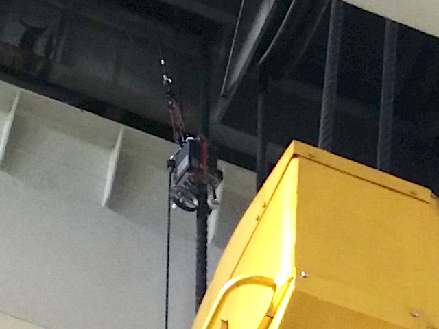
Inspection of the « dead point » section
The operating mode used to inspect the dead point of the hauling system consisted of:
- place the hook in the low position,
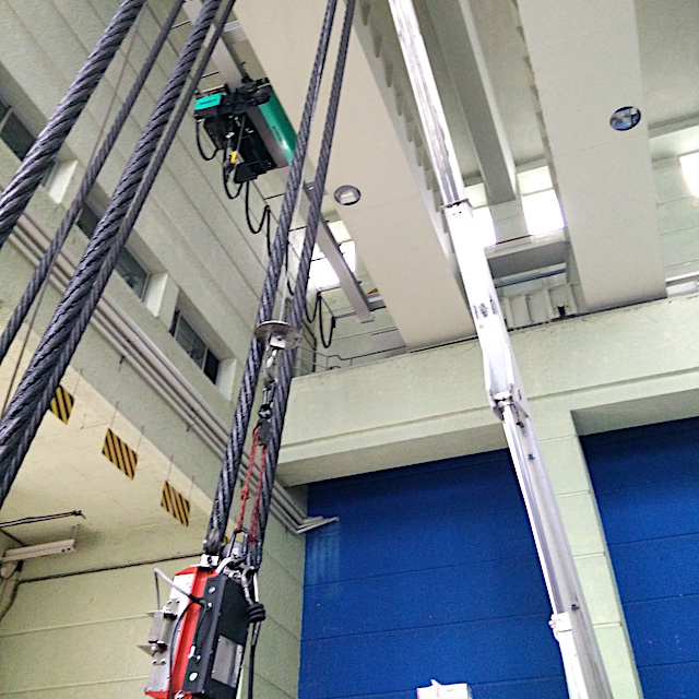
- suspend a pulling winch at the head of the traveling crane,
- install the Rotec U58 machine just above the hook,
- move the machine back and forth at a speed close to 0.3m/s to record the magnetic signals.
It is important to note that the data acquisition is controlled by an encoder wheel with an accuracy of 2 samples per millimeter. The measurement finally includes the position, the instantaneous speed, the channels of two radial leakage flux sensors LF1 and LF2, the axial channels LMA (loss of metallic area) and LF (axial leak flux) as well as the complementary recording of 46 Hall effect sensors arranged in a ring and intercepting an angular sector of 7.8 degrees of the rope section.
Magnetic rope testing of the dead point of crane PR-175-20


Wirelet analysis of magnetic signals
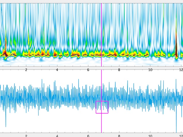
The magnetic signals were analyzed using Wirelet software to decide on the condition of the ropes. The following diagrams illustrate for example:
- Wirelet analysis of magnetic signals
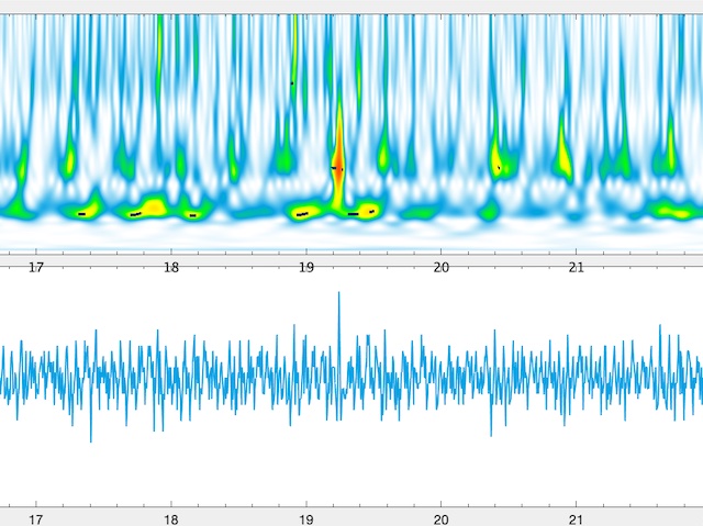
- A sequence of typical energy signatures of wire wear by abrasion, concentrated on the first winch windings of the rope, which here corresponds to the rope section that is most often used during lifting operations.
- A W2 broken wire signature, present on the second crown layer of the Warrington-Seale construction.
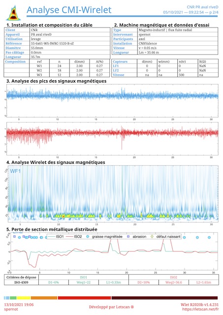
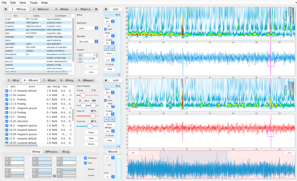
The Wirelet software, a snapshot of which can be seen below, allows the analysis in supervised mode of all rope anomalies according to the criteria of the ISO4309 lifting standard.


MRT-Wirelet report
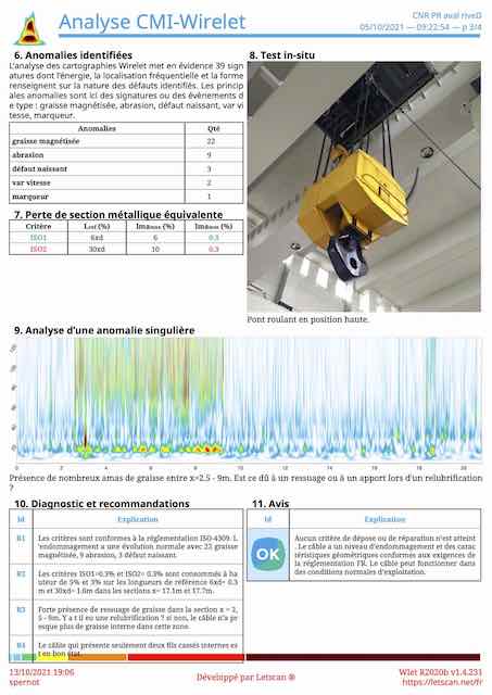
The proprietary Wirelet software not only makes it possible to analyze all steel wire rope anomalies but also to edit in a single click a complete analysis report including:
- the distribution of anomalies along the rope and the monitoring of indicators in terms of damage severity
- the detailed list of anomalies and their inner characteristics,
- the conclusions on the ability of the cable to be used under normal operating conditions,
- some recommendations for preventive actions to preserve the life of the rope.